Finding Circuit Opens and Shorts
Over the years, I have dealt with plenty of electrical problems, some were easy, others you would take home and have nightmares. After forty years of this
profession I have learned more than one way of doing things, sometimes it would boil down to how I felt like doing it. One thing for certain, you will need
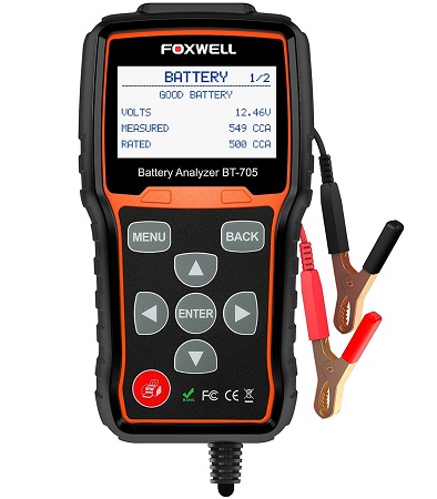
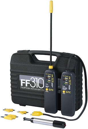
some tools to allow you to tackle the electrical system problems you will face in the automotive world. From left to right below, a good battery tester is in
order, most of them will load test them as well as test the starting, and charging systems. A good circuit tester is essential as well, this will allow you to
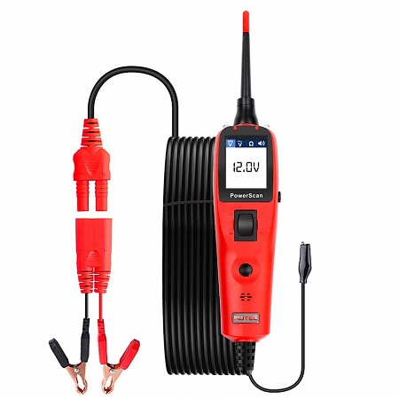
locate shorts and opens, sometimes you may find them without one, if your lucky. At least a decent test light, or you could opt for a good power probe,
these give you a lot of control for testing over a plain test light. Just these three things will be the least you will need to get you started in this kind of work.
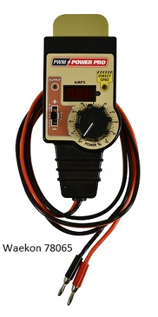
I've added another item to this list, this unit should be highly valuable in this line of work Waekon's Power Pro, I wish this had been around in my time.
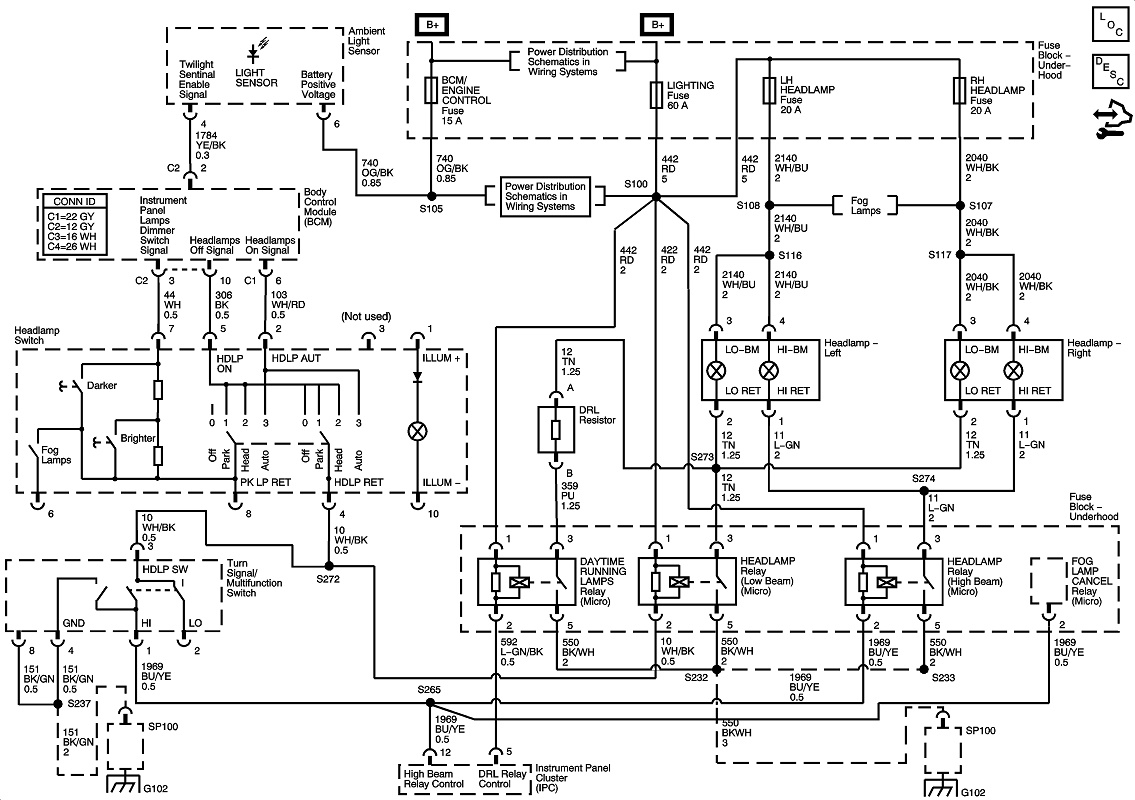
I want to use the diagram below and create some scenarios to give you an idea how I would approach problems based on what we find. The first problem is the
low and high beam headlights do not operate on either side of the vehicle, so after looking at the diagram, now what? Hopefully you can read a diagram, you will
need that ability to get anywhere with this work, obviously, we will check fuses first, the first would be the lighting fuse, a 60 amp most likely maxi fuse in the
under hood fuse block, if its good we go next to the headlamp fuses, there is one for each side of the vehicle, LH and RH, in this scenario, we find no power at both
fuses on both sides of the fuse, but we have power at the 60 amp lighting fuse on both sides of the fuse, between the 60 amp lighting fuse and the headlight fuses,
we find a wire to a splice that leads off in five directions, S100, the wire from the fuse to the splice, and from the splice going to the two headlight fuses is what we
are interested in, and since we find the 60 amp fuse good with power on it, it has to be an open in the wire between the fuse and the headlamp fuses. Its in a small
enough area, so it should be easy to find, after looking at it, if it seems intact visually, use your circuit tester, it may be a break inside the wire insulation.
So now you find one headlight not working on the LH side, so once again, we are checking fuses, this time we find a blown fuse on the LH side
headlight fuse, when checking both sides of the fuse with your test light, you find power on one side, but not the other indicating such. When you have a
blown fuse, more current passed through the fuse than its rating was capable of handling, possibly a shorted wire or component on the circuit so, you
should find the other side of the fuse will show a ground, to find out, put your test light clip to power and check the other side of the fuse, if it lights, there
is a ground on that side of the fuse, now you know what caused the fuse to blow, now you need to find out why, its most likely a shorted wire to ground
some where from the fuse to the headlight, since it will be easier to go to the headlight first, start there and work your way back. first use your eyes,
then if you need to, use your circuit tester and trace it all the way back to the fuse block, this is when it gets tough when you need to trace through wiring.
How The Fuses Work
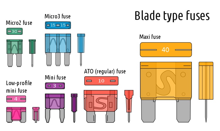
An automotive fuse
consists of a metal strip or wire fuse element, of
small cross-section compared to the circuit
conductors, mounted between a pair of electrical
terminals, and (usually) enclosed by a non-combustible housing. The fuse is arranged in series to carry all the current passing through the protected circuit. The
resistance of the element generates heat due to the current flow. The size and construction of the element is (empirically) determined so that the heat produced for a
normal current does not cause the element to attain a high temperature. If too high a current flows, the element rises to a higher temperature and either directly melts,
or else melts a soldered joint within the fuse, opening the circuit. The fuse element is made of zinc, copper, silver, aluminum, or alloys to provide stable and predictable
characteristics. The fuse ideally would carry its rated current indefinitely, and melt quickly on a small excess. The element must not be damaged by minor harmless
surges of current, and must not oxidize or change its behavior after possibly years of service. An electrical fuse is a device that sacrifices itself to provide over-current
protection in an electrical circuit. Conducting wires have a small electrical resistance. The electrical resistance of a conducting wire is related to the type of metal
used and inversely related to the cross-sectional area of the wire. The larger the diameter of a wire, the greater the cross-sectional area,and the lower the electrical
resistance will be. When electrons flow through a wire, they repel each other and interfere with the passage of other electrons. If there are a very large number of
electrons (high current) passing through a wire with small diameter, the electrons will experience a greater resistance than if the wire diameter were larger and the
electrons had more space between them. Check out a case study I did that will give a good example of some of what can be found relating to this, here.

In this scenario, I want to show just how hard it can be dealing with some problems, in this case, we have low beams on both sides, but no high beams
on either side. So what do we start with first? Of course we check fuses the same way, and we find the 60 amp lighting fuse good with power on both sides
of the fuse like before, and the LH and RH headlight fuses are both good with power on both sides of the fuses, from here we go to the headlight bulbs and
see if power is getting to the bulbs on the high beam side, (4) in this case it is, so with power to the bulbs, we need to check the bulbs, both have good elements
in them when we put power on them to test them, so they are ok, now what? Looking at the diagram, we can see that the grounds to the bulbs (1) are controlled
by a body control module through relays for the, low beam, and high beam lighting, now we need to look at this side of the bulb, the ground side, (1) a whole
new area, and a bit more complex, we may even have to get a scan tool hooked up, now, since the power side of the high beams exists, but the bulbs don't
operate, we know there can't possibly be a ground, to the bulbs, (1) what to do next, check the bcm and see if its commanding the relay on through the high
beam switch, and if it is, is the relay responding to the command with a ground to the relay, is the relay switching the ground to the bulbs, are the grounds
getting to the bulbs, now you see what I meant, a whole lot of possibilities, a lot more complex problem, a lot of testing involved here, that's why this can
be mind bending about how to make the job go as fast as it can with your choices. So what would you do next? How about a quick relay swap, most likely
that low beam relay will be an exact match to the high beam relay, and would be an easy way to see if its bad. Well, in this case its not, most often its not
the relay. Next, I would pull that relay and see if the ground (G102) that would be switched by the relay to the bulbs is good, and it is, next? lets check for
codes in the bcm and there are none, and there wouldn't be anyway for this issue, since the command would be sent down one circuit in two directions,
one for low beams, and one to the high beam switch to activate the high beams, and that is what we find failed, the contacts are burnt out in it. What if
we had no ground to the bulbs from the relay? Then it would have been a wiring problem between the relay and grounds to the bulbs. A lot of these
relays are being built into the relay center in some newer models, (I can't imagine why, $$$) and are not serviceable with out replacing the whole thing.
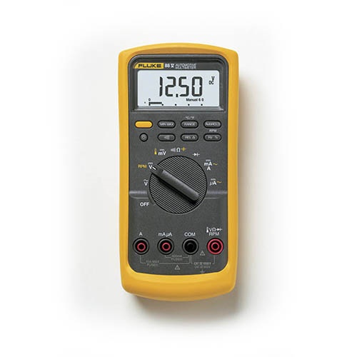
If your going to get a DMM, don't think twice, this is the one you want, save your
money until you can get it, anything else, forget it, a waste of money, the best of the best!
Fluke 88V Series V Deluxe
True RMS AC voltage and current for accurate measurements on non linear signals
0.1% DC accuracy
Current measurements up to 10 A, 20 A for up to 30 seconds
Millisecond pulse width measurements for fuel injectors
Min/Max/Average recording with Min/Max Alert to capture variations automatically
Peak Min/Max records transients as fast as 250 μs
Relative mode removes test lead resistance from low ohms measurements
Auto and manual ranging for maximum flexibility
Autohold captures stable readings with only one touch of leads
Analog bargraph to track changing or unstable signals
Input Alert provides audible warning against wrong use of input jacks
Access door for fast battery changes without opening case
"Classic" design that fits your hand with new removable holster, built-in test lead and probe storage
10 meg ohm input impedance will not damage computer circuits
terminals, and (usually) enclosed by a non-combustible housing. The fuse is arranged in series to carry all the current passing through the protected circuit. The
resistance of the element generates heat due to the current flow. The size and construction of the element is (empirically) determined so that the heat produced for a
normal current does not cause the element to attain a high temperature. If too high a current flows, the element rises to a higher temperature and either directly melts,
or else melts a soldered joint within the fuse, opening the circuit. The fuse element is made of zinc, copper, silver, aluminum, or alloys to provide stable and predictable
characteristics. The fuse ideally would carry its rated current indefinitely, and melt quickly on a small excess. The element must not be damaged by minor harmless
surges of current, and must not oxidize or change its behavior after possibly years of service. An electrical fuse is a device that sacrifices itself to provide over-current
protection in an electrical circuit. Conducting wires have a small electrical resistance. The electrical resistance of a conducting wire is related to the type of metal
used and inversely related to the cross-sectional area of the wire. The larger the diameter of a wire, the greater the cross-sectional area,and the lower the electrical
resistance will be. When electrons flow through a wire, they repel each other and interfere with the passage of other electrons. If there are a very large number of
electrons (high current) passing through a wire with small diameter, the electrons will experience a greater resistance than if the wire diameter were larger and the
electrons had more space between them. Check out a case study I did that will give a good example of some of what can be found relating to this, here.

In this scenario, I want to show just how hard it can be dealing with some problems, in this case, we have low beams on both sides, but no high beams
on either side. So what do we start with first? Of course we check fuses the same way, and we find the 60 amp lighting fuse good with power on both sides
of the fuse like before, and the LH and RH headlight fuses are both good with power on both sides of the fuses, from here we go to the headlight bulbs and
see if power is getting to the bulbs on the high beam side, (4) in this case it is, so with power to the bulbs, we need to check the bulbs, both have good elements
in them when we put power on them to test them, so they are ok, now what? Looking at the diagram, we can see that the grounds to the bulbs (1) are controlled
by a body control module through relays for the, low beam, and high beam lighting, now we need to look at this side of the bulb, the ground side, (1) a whole
new area, and a bit more complex, we may even have to get a scan tool hooked up, now, since the power side of the high beams exists, but the bulbs don't
operate, we know there can't possibly be a ground, to the bulbs, (1) what to do next, check the bcm and see if its commanding the relay on through the high
beam switch, and if it is, is the relay responding to the command with a ground to the relay, is the relay switching the ground to the bulbs, are the grounds
getting to the bulbs, now you see what I meant, a whole lot of possibilities, a lot more complex problem, a lot of testing involved here, that's why this can
be mind bending about how to make the job go as fast as it can with your choices. So what would you do next? How about a quick relay swap, most likely
that low beam relay will be an exact match to the high beam relay, and would be an easy way to see if its bad. Well, in this case its not, most often its not
the relay. Next, I would pull that relay and see if the ground (G102) that would be switched by the relay to the bulbs is good, and it is, next? lets check for
codes in the bcm and there are none, and there wouldn't be anyway for this issue, since the command would be sent down one circuit in two directions,
one for low beams, and one to the high beam switch to activate the high beams, and that is what we find failed, the contacts are burnt out in it. What if
we had no ground to the bulbs from the relay? Then it would have been a wiring problem between the relay and grounds to the bulbs. A lot of these
relays are being built into the relay center in some newer models, (I can't imagine why, $$$) and are not serviceable with out replacing the whole thing.

If your going to get a DMM, don't think twice, this is the one you want, save your
money until you can get it, anything else, forget it, a waste of money, the best of the best!
Fluke 88V Series V Deluxe
True RMS AC voltage and current for accurate measurements on non linear signals
0.1% DC accuracy
Current measurements up to 10 A, 20 A for up to 30 seconds
Millisecond pulse width measurements for fuel injectors
Min/Max/Average recording with Min/Max Alert to capture variations automatically
Peak Min/Max records transients as fast as 250 μs
Relative mode removes test lead resistance from low ohms measurements
Auto and manual ranging for maximum flexibility
Autohold captures stable readings with only one touch of leads
Analog bargraph to track changing or unstable signals
Input Alert provides audible warning against wrong use of input jacks
Access door for fast battery changes without opening case
"Classic" design that fits your hand with new removable holster, built-in test lead and probe storage
10 meg ohm input impedance will not damage computer circuits