Most of us can visualize an engine going through it's chore of sucking and blowing, how well it's blowing is easy to verify on the 5 gas, how well it's sucking is easy with a vacuum gauge, if it's not sucking so well, a vacuum probe will help you find out why. I have looked at several different Vacuum Probes for use on a Basic Scope, and none seemed to give the resolution needed to be of much use in telling whats going on during intake events, I decided that to get what I wanted, I would build my own from inexpensive parts easily assembled by any Tech. A lot of time went into coming up with something that worked.
Above is an image using a Fluke PV 350 Pressure-Vacuum Transducer. I won't go into detail on this, you can see it doesn't tell you much about the per cylinder vacuum pulses in the vacuum signal. They are there, but not very informative.
The Fluke has two settings, Metric or SAE, this image is in the metric setting, same vehicle as above. Somewhat better here, but still not good enough for me. It picks up a lot of ignition noise. This thing is great for looking at fluid pressure changes on road tests, but for vacuum signals, it doesn't cut the mustard in my opinion.
The image above is from my final design using a OEM style transducer. This waveform was captured from a Port injected Honda 4cyl, at the hose to the power brake booster, triggered off the #1 Injector. Trace (A), are the actual per cylinder vacuum pulses hidden in the vacuum signal. Getting them to show in a scope waveform at a resolution that has any meaning is not easy. During my research, there were many different variables.
Here is the schematic, using a GM map sensor #16006835. Some of you may know that Integrated Circuits (IC's) run on a broad range of voltages. To get the voltage output low enough to be seen on the scope at a scale that gives any meaning to the vacuum signal requires adjusting input and output voltages, this is the reason the voltage amount has no meaning, the only interest is the waveform itself. This transducer would not produce a signal at under about 2 Volts. So I started at about 2.5 Volts by adjusting volts to the transducer (measured at the output, with no vacuum signal applied) with the 5Kohm pot. Further fine adjustment is made on the output signal with the 1megohm pot (while viewing the vacuum signal) . This thing can be put together in any type project box, the easiest would be a plastic one. Radio Shack, or your local electronics store will have all you need to build one, with the exception of the transducer, and the pigtail for it, get them from your local AC-Delco supplier, or GM if you have to. I used a pot switch on the pot controlling volts to the transducer to turn the unit on and off. A female bnc connector hooks it to my scope for the output signal, banana jacks could be used if required. Here are some images of my completed unit.
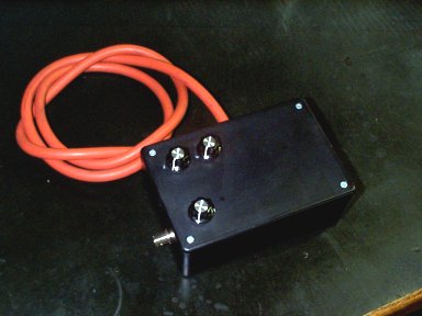
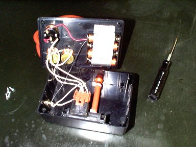
The adjustment pots will help move the trace up and down on the scope to make the signal viewable at a low volts scale, some as low as 50mv/perdiv. This makes the pulses from each cylinder more readable. Four cylinder engines will give the best signal, since there are only four pulses to view. More cylinders will bring the resolution down further, so adjustment is required. Where to get the vacuum signal will also affect readings, and engine rpm will change it as well. The signal can be viewed off the hose to the power brake booster with adequate results. Where the hose is attached to the intake manifold may, or may not affect the signal, try other points available for better results, just going from the power brake booster to the pcv valve source on one made a huge difference in the quality of the signal. Use a vacuum gauge to see amount of signal in conjunction with the probe. I used 1/4" Silicone tubing with a 1/4" to 3/8" nipple to adapt to the power booster hose. Pigtail for the transducer is a AC-Delco piece. You will notice I have three pots on my unit, this was left over in the box during research, and is no longer in use. Battery holder is a simple four AA holder, I taped the batterys in to keep them from falling out. I suppose it looks somewhat crude, but it does work. Keep in mind this thing is experimental, I offer no guarantee of success with it, I have yet to see anything bad with it, most of what I work on is late model low mileage stuff, so I get no real opportunity to use it. What I would like to see its results on, would be a bad cam lobe, or maybe an import 4cyl in need of a valve adjustment.
Triggering off the number one injector will show the pulses in firing order, in these images the vacuum trace is a series of peaks with the injector firing beginning in line with the top of the peak in the vacuum trace, proof that this thing works, (I was amazed!) if the time base were more compressed, you would see number one injector firing again with four pulses in between, injector firing will move the vacuum trace around slightly with rpm change. This is the start of the intake stroke for that cylinder. Up towards the top of the peak, on the downward leg, you will notice a small hump in the trace, This would be the point of intake valve going completely open just after the overlap period, this results in a small drop in vacuum. As piston speed increases after going past tdc, the leg down past the hump should show a slight curve as vacuum increases. Then as the intake valve starts closing at the bottom of the leg, vacuum begins to drop off. This resolution may or may not be seen in 6 or 8 cylinder engines, it gets lost in the bigger displacement. Keep in mind the only thing seen in the trace is the time the intake valve is open, and the time in between its closing and opening of the next cylinders intake valve in firing order. No other event in the cylinders combustion process is seen. Its important to keep that in mind.
Weak filling cylinders from poor sealing valves, rings, or a loss of volume from short valve lift for any reason, should show as a dropped peak. Since the triggering is off #1 injector here, the offending cylinder is easy to find.
Late valve timing (cam timing, very loose, or slipped chain, belt) should show as clipped peaks, and will be affecting all cylinders (loss of filling on all cylinders).
Triggering off #1 ignition will require an understanding of which cylinders are starting their intake stroke when number one begins its power stroke, since this is when the ignition is occuring. It isn't that hard to figure from any firing order. Once you know the order on any engine, take the last half of the cylinders from the firing order, and write them under the first half, and you will know the mating cylinders (cylinders that are paired). When number one is on its power stroke the mating cylinder is at the end of its exhaust stroke, and actually beginning its intake stroke (Overlap period), both pistons are on their way down the in the cylinder at the same time, one does its power stroke, the other is on its intake stroke. From this, you can tell which cylinder in firing order is in the vacuum trace. The image above shows a carb inducted Chev 350 at the pcv nipple at the base of the carb (better here than at power brake booster), triggered off #1 ignition. The last half of cylinders in the firing order are, 6,5,7 and 2. So the mating cylinders are 1 and 6, 8 and 5, 4 and 7, 3 and 2. The first peak after number one firing is always the mating cylinder to number one, in this case, number one mating cylinder is number six, so its the peak right after the ignition spike of number one. Don't let this confuse you, remember, all you see in the vacuum trace is one stroke of the cylinders four strokes of the combustion process. You might think that since number eight is next to fire, that it should be right after number one firing. In this engine there are 32 strokes during all eight cylinders completed firings. In the trace, we only see eight of them.