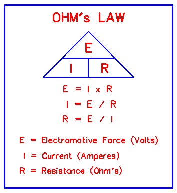
Parasitic Draw
The term Parasitic Draw refers to electrical devices that continue to use or draw current after the ignition switch is turned off. This small amount of continuous battery
draw is expressed in milliamps (mA). On Ford Motor Co. and General Motors vehicles produced after 1980 MY, a typical Parasitic Load should be no more than 50mA.
I'm going out on a limb and say my limit is 85mA on newer beyond 2000 MY, to 100mA on beyond 2010 MY, assuming you find nothing to attribute it too. Vehicles produced
since 1980 have memory devices that draw current with ignition off for as long as 20 minutes, on older MY's, to two hours, on newer MY's, before shutting down the
Parasitic Drain. When Parasitic Load exceeds normal specifications, the vehicle battery will go dead, overnight, or in a few days, depending on the size of the drain.
The key to long life for any battery is to make sure battery voltage doesn't drop below 12.4 volts. The combination of a significant parasitic draw and long periods of
non-use can easily cause voltage to drop below 12.4 volts. When that happens, sulfation begins to diminish both capacity and performance. If you have an 85-milliamp
draw in a car with a single 50Ah battery, as is the case in most vehicles, your battery will be completely discharged from a full state of charge in just over three weeks.
If the vehicle is going to sit for long periods of non use, disconnect the battery. Pay close attention to the battery top, if it appears wet and dirty, give it a good wipe,
that accumulation will also slowly discharge the battery. Use of NoCo oil based battery terminal protectors will help keep corrosion to a minimum is a good practice.
TEST PROCEDURE USING TEST SWITCH
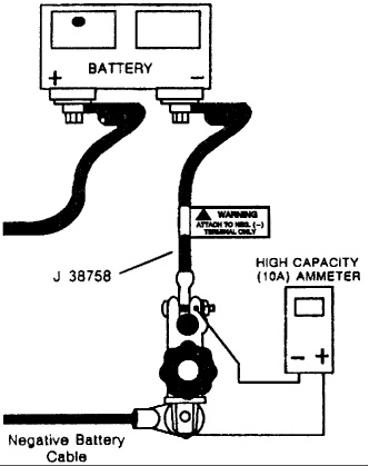
Fig. 1
Check battery
voltage, make sure its at least 12.4v, remove negative
battery cable terminal,*
install disconnect tool, (J-38758) test switch male end to negative battery
cable, turn test switch knob to OFF position, install
negative battery cable to the female end of test switch,
turn test switch knob to ON position, (current through
switch), make sure ignition switch is in LOCKED position and
remove key, and fob from the vehicle, connect ammeter (I'm
not crazy about using inductive probes, see why) terminals to test switch terminals, see Fig. 1, select the highest amp
scale, turn off all electrical accessories, turn off
interior lights, under hood lamp, trunk light, illuminated
entry, etc, to avoid damaging ammeter or obtaining a false
meter reading, all accessories must be off and
time allowed for all systems to enter sleep mode (I allow a minimum two hours on late MY's to make sure) before turning test switch knob to OFF position, (I recommend a fused 5 - 8A test lead to protect your DMM fuse) turn test switch knob to OFF position to allow current to flow through ammeter, observe current reading, If reading is less than 2 amps, turn test switch to ON position to keep electrical circuits powered-up, select low amp scale, turn test switch to OFF position and compare results to normal current draw, If current draw is unusually high for the vehicle’s overall electrical system, give the car a good visual look, is the dome on, could be a door ajar switch, is the trunk shut, there are all kind of things to look at, the two things I found most, visor lights, and glove
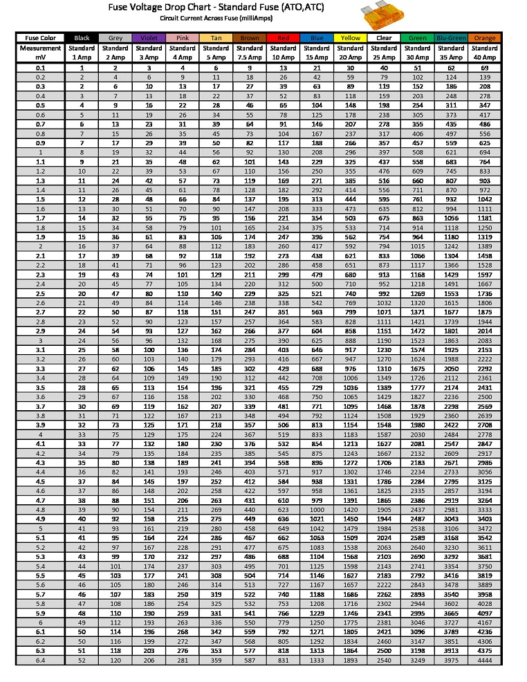
box lights, after this, check and see if the alternator may be causing the draw by disconnecting it totally from the system and recheck, if the draw still exists, connect it back up and continue to the main maxi fuses (if equipped), you are only going to check the ones that have battery volts on them, not the ones that would power up with the key on, and check for any voltage drop across them (voltage drop charts) (make sure there is no under hood lamp or hood ajar switch) Any reading here in drop would point to where you go next by looking at a diagram for the application your working on, now you will know what fuses to check to narrow it down, fuses with out test points will be a problem, so replace them with fuses with test points before you start your testing. Why couldn't you use a test light to check for an indication of a draw? Why not? If you have one of those with the fuse style bulb, that only requires 150ma to light up, which would be about where you would go looking for an excessive draw, you just connect the test light the same way you would your ammeter, if the light is on, its at least enough to turn the light on. you could still check the fuses for voltage drop, or you could just pull fuses one at a time, to see if the light goes out.
*You could save the connection to the battery by using a jumper battery, then remove the ground terminal, then connect the ammeter, then disconnect the jumper battery, this would negate the need for the disconnect switch.
time allowed for all systems to enter sleep mode (I allow a minimum two hours on late MY's to make sure) before turning test switch knob to OFF position, (I recommend a fused 5 - 8A test lead to protect your DMM fuse) turn test switch knob to OFF position to allow current to flow through ammeter, observe current reading, If reading is less than 2 amps, turn test switch to ON position to keep electrical circuits powered-up, select low amp scale, turn test switch to OFF position and compare results to normal current draw, If current draw is unusually high for the vehicle’s overall electrical system, give the car a good visual look, is the dome on, could be a door ajar switch, is the trunk shut, there are all kind of things to look at, the two things I found most, visor lights, and glove
box lights, after this, check and see if the alternator may be causing the draw by disconnecting it totally from the system and recheck, if the draw still exists, connect it back up and continue to the main maxi fuses (if equipped), you are only going to check the ones that have battery volts on them, not the ones that would power up with the key on, and check for any voltage drop across them (voltage drop charts) (make sure there is no under hood lamp or hood ajar switch) Any reading here in drop would point to where you go next by looking at a diagram for the application your working on, now you will know what fuses to check to narrow it down, fuses with out test points will be a problem, so replace them with fuses with test points before you start your testing. Why couldn't you use a test light to check for an indication of a draw? Why not? If you have one of those with the fuse style bulb, that only requires 150ma to light up, which would be about where you would go looking for an excessive draw, you just connect the test light the same way you would your ammeter, if the light is on, its at least enough to turn the light on. you could still check the fuses for voltage drop, or you could just pull fuses one at a time, to see if the light goes out.
*You could save the connection to the battery by using a jumper battery, then remove the ground terminal, then connect the ammeter, then disconnect the jumper battery, this would negate the need for the disconnect switch.
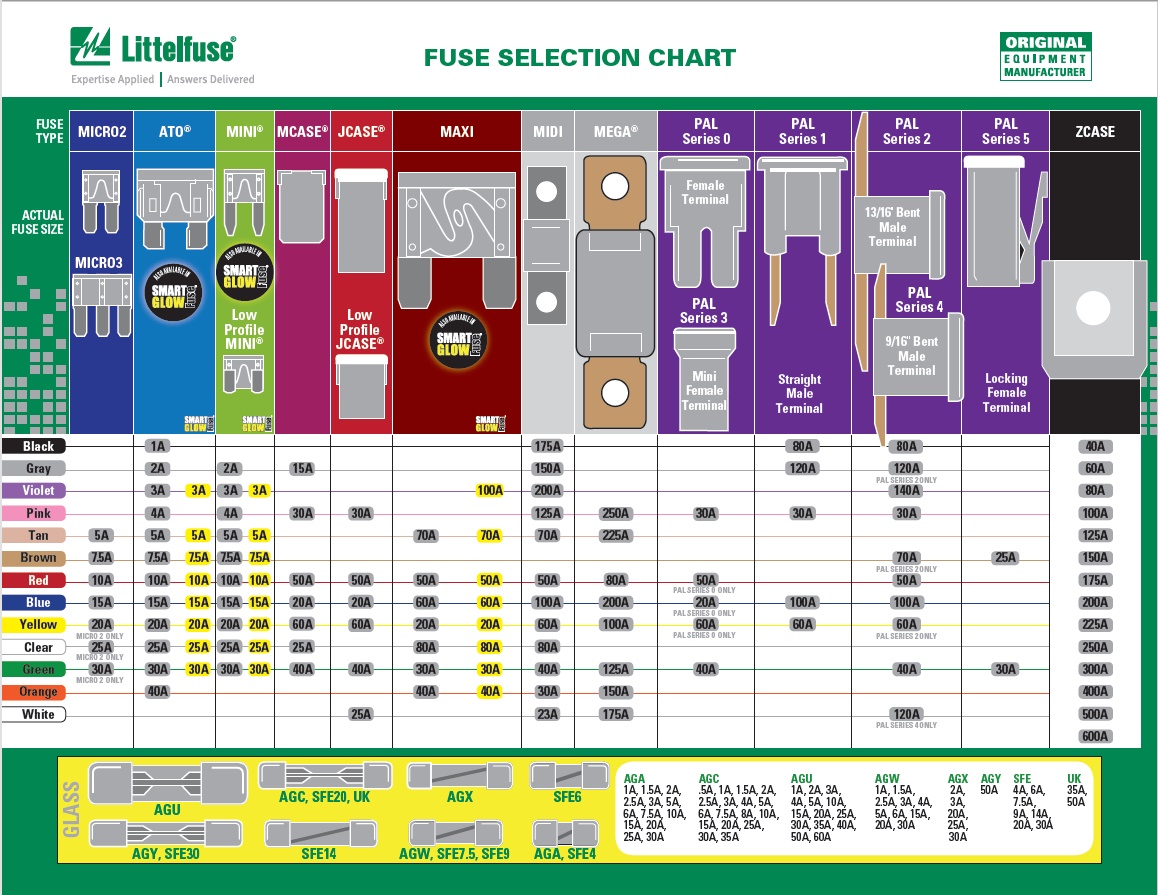
When is it safe to use a bigger fuse?
NEVER!
Never ever use a fuse of higher value than is specified, it could possibly burn the vehicle to the ground!