GM Integrated Direct Ignition (IDI)
Here are some images captured from an 89 GM Quad 4 engine with IDI Ignition.

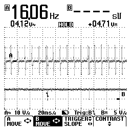
Crankshaft Position Sensor (A), 1X signal (B), triggered on 1X signal. CKP pulses are 60 degrees apart with the exception of the sync signal shown here lining up with the 1X pulse on (B). The image below shows the detail.
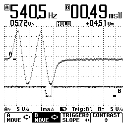
In this image the Crankshaft position sensor (A) is showing the #6 pulse and #7 pulse. The #7 pulse is the Sync pulse, and is 10 degrees after the #6 pulse. The 1X signal (B) is created by the ignition module off the sync pulse from the CKP sensor. In this image the scope is being triggered of the 1X signal to show its relationship to the sync pulse. PCM uses 1X signal for injector timing.
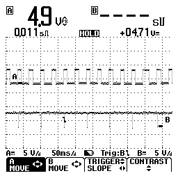
2X signal (A), 1X signal (B). Ignition module sends PCM a 2X signal as the reference signal. Here it is with the 1X signal triggered off same, showing two pulses per engine revolution hence the term, 2X. Ignition module divides and filters the CKP signal to create these two signals and sends them to the PCM for use in spark timing and injector control.
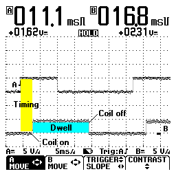
Timing control on IDI ignition, (A) 2X signal (B) EST signal 2000 RPM.
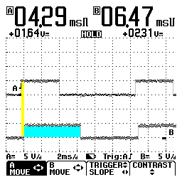
Timing at idle
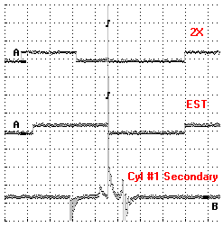
This image shows where the coil is firing, in relationship to 2X and EST signals. All three traces are drawn triggered off the #1 cylinder secondary spike.