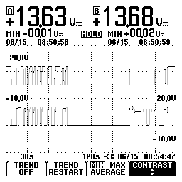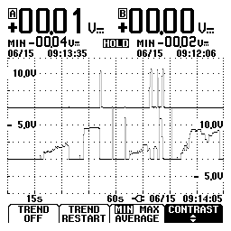
Below are images of some signal plots on a 90 Acura Legend 2.7 V6 intermittent no start. Proof of the value of plotting signals.

In this image, fuel pump power out to pump is the top trace, power in is the bottom trace. These signals are taken at the PGM-FI main relay. Prior to checking signals at the relay, power at the pump itself was checked and wasn't getting there during the no start. After going to the relay to plot the signals, power was also missing out of the relay. In the traces above, the first third part of the two signals show normal start, run, and shutting off of the engine. Then a keyoff period of about a minute and half, then when tried again the no start showed up as a loss of power to the pump, power in is still going into the relay, eliminating it as a factor. Now the other relay signals can be plotted.

In this image, PCM pump control is the top trace, crank signal the bottom trace.

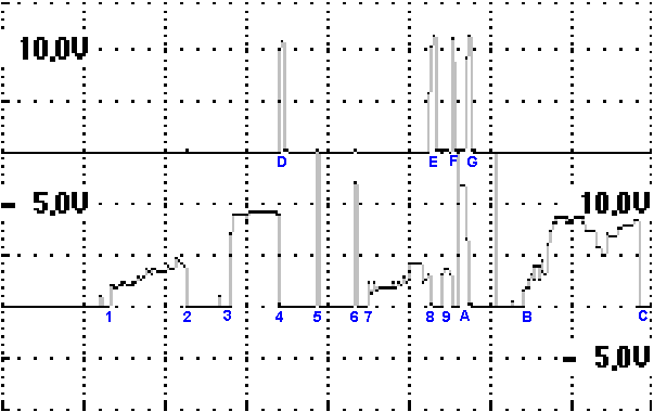
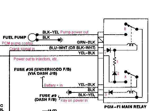
I enlarged this image to see more detail, so I could explain each trace a little better by numbering each event in the trace. Starting with (1) KOEO voltage is seen at the crank signal input (bottom trace) terminal and is slowing rising in amplitude. Voltage should not be at this terminal unless cranking signal is on it. The internal diode (1) in the relay is obviously shorted and voltage is leaking past it.
Voltage should be on the PCM side (top trace) of the relay coil that would activate the points to send pump power. (2) is K-OFF (3) is KOEO and this time voltage rises quickly to almost battery volts. (4) is K-OFF (D)-(G) Periodic signals appear at PCM pump control. (5), (6) Voltage spike from points (A) closing. (7)-(C) More of same. None of these signals should be seen on this side of the diode. I think there are several problems with this relay, surely a bad diode (1) possible burnt points (A) intermittent diode (2) bad resistor (1) cold solder joints on circuit board. Pump relay fixed it.
