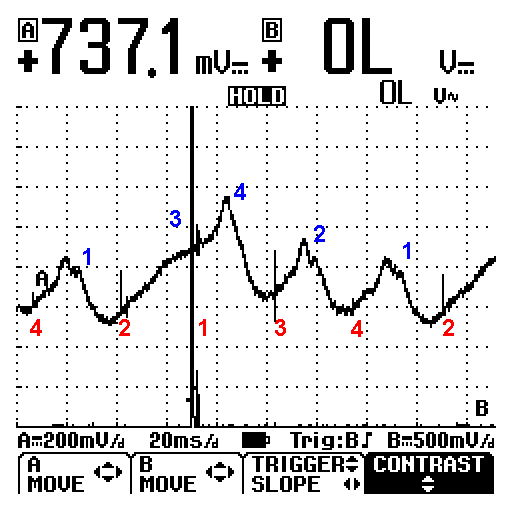
I have learned from this case study how my Vacuum probe really works.


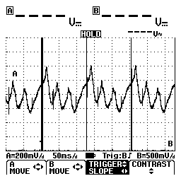
I had thought that the peak prior to number one was the mating cylinder for it in the vacuum trace, turns out I made an incorrect assumption, here's the proof. In the image above from a 94 Ply Acclaim 2.5 TBI 4cyl, number three cylinder is dead and this is how it shows up in the vacuum trace, the peak prior to number one firing is missing. Since number four is next in vacuum pulse firing order, it has to be the next peak in the trace. This is the peak following number one ignition firing. So this is the way they will show in the waveform. I verified this.
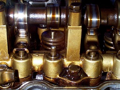
The two valves on the left are number three, exhaust on the left, intake on the right. The follower for the intake got loose from the valve stem sticking in the guide and fell out. (was laying behind the valve springs) The valve hanging open was the reason for the pumping loss in the vacuum trace. A few shots of penetrant loosened up the valve, and after putting back together, the vacuum waveform is much better. (below)
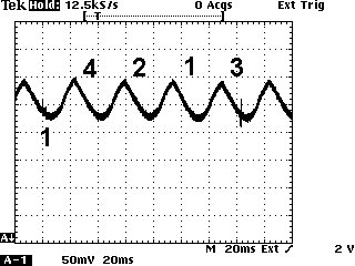
I had to use my Tek for these, the battery on the Fluke needed charged.
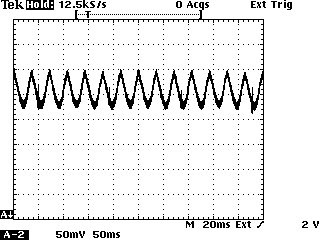
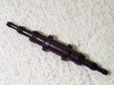
Tip: I have found that using one of these multi size vacuum line connectors in the vacuum line to the probe helps clean up the waveform by dampening the pulses somewhat, this was used to produce the waveforms above. The first waveforms on this page were not using this dampening in the hose.