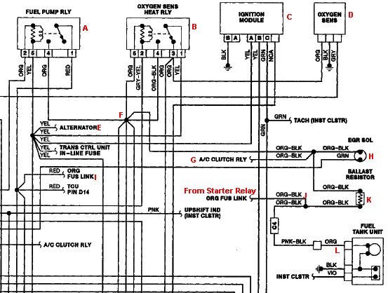
Here is the pump circuit wiring diagram for this application, a techs nightmare to understand. A lot of time spent here to find the proper place to look at the signal, and to understand how it all works. A very complicated setup to say the least, lets start with the pump relay first. Getting the signal at the relay socket with engine running will show draw including many other components as you can see in the diagram originating at (F) 1. O2 heater relay (B), 2. EGR Solenoid (H), 3. A/C Clutch Relay (G) 4. Injector Feed to ECM (not shown) All this is bypassed during cranking since the starter relay is powering the pump through (J). All these components may or may not be operating at any given time, so best to find another place to acquire the signal. This setup also uses a Ballast resistor in the pump circuit to reduce noise of the pump. Best place to view signal is the pump side of the resistor, between (K) and (L).
Looking at the signal after the ballast resistor lowers current to the pump and doesn't provide much in the pattern to read in this case, find the starter relay, and send power to the pump through the wire that feeds the pump during cranking will produce a better signal, even though you won't verify the complete pump circuit.
Powering the pump through starter relay feed wire, gives a better pattern, this is more readable. This pump is very noisy, and the pattern indicates a high variation of draw, indicating fluctuating rpm. This pump should develop about 30-40 PSI, so draw is low, rpm is not a factor since its fluctuating so much, if you read it here, 3076 rpm (12 segment pump).